Hidrografi
Calibration and Patch Test for Multibeam Echosounders
A multibeam echosounder's spec sheet promises centimetre-level depth accuracy. What that spec sheet doesn't mention is that the sonar head, the motion sensor, and the GNSS antenna are all bolted to the vessel slightly out of perfect alignment with each other — and that tiny misalignment, left uncorrected, quietly bends every sounding the system collects. The patch test is the procedure that finds and removes that bend before a single line of production data is logged.
What a Patch Test Actually Calibrates
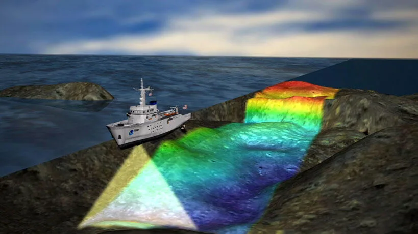
A patch test isolates four specific error sources, each one a small rigid-body misalignment or timing offset that would otherwise bias every sounding the system records. Three of them are boresight angles — small rotational offsets between the motion sensor's reference frame and the sonar head's own frame: roll, pitch, and yaw (heading). The fourth is latency, a timing offset between when a position/attitude fix arrives and when the acquisition system actually applies it to a given ping. None of these four values can be measured directly by inspecting the installation with a tape measure; they only reveal themselves as depth and position errors in the data itself, which is exactly why a dedicated test procedure exists to isolate each one in turn.
The Test Sequence and Site Requirements
Each of the four parameters is isolated with its own site conditions and its own survey geometry, and the standard practice is to calculate them in a specific order — time delay first, then pitch, then roll, then heading — because an uncorrected error earlier in the sequence can contaminate the estimate of the ones that come after it.
Latency
Latency is isolated by running the same line twice over identifiable seabed features at two distinctly different vessel speeds — for example, once at roughly 3.5 knots and again at roughly 7 knots. A timing offset between the position feed and the sonar ping shows up as a positional discrepancy between the two passes that scales with speed, which is what lets the offset be measured and separated from the boresight angles.
Pitch
Pitch calibration requires a sloping seabed, ideally with a gradient somewhere between about 1:2 and 1:5, surveyed in two opposite directions — once running up the slope, once running down it. An uncorrected pitch offset shows up as a discrepancy in depth that grows steadily larger with distance from the swath centre, a signature that becomes progressively easier to see the further out along the slope the comparison is made.
Roll
Roll is calibrated over a flat seabed, again surveyed in two opposite directions along the same line. With a single-head system this means one reciprocal line pair; dual-head systems typically use three parallel lines with a lateral offset between them. Roll is usually treated as the most sensitive of the three boresight angles to get right, because a roll residual doesn't just blur the swath edges — it systematically tilts the entire cross-section, making one side of the swath read too shallow and the other side too deep.
Yaw (Heading)
Yaw is resolved using a distinct seabed target or feature, surveyed on crossing or parallel overlapping lines — two lines for a single-head system, three for dual-head — with a lateral spacing between lines of roughly 1.5 times the water depth to keep the geometry sensitive to the error being measured. Because the swath edges are where a heading error is most exaggerated, this test depends on the outer beams of overlapping passes actually seeing the same feature from different angles.
Why Getting This Wrong Is Expensive
IHO S-44 doesn't leave calibration as a matter of professional preference — it states plainly that survey equipment "should be free of systematic errors which must be determined by calibration and qualification." An uncorrected roll residual, for instance, doesn't average out over a survey; it introduces a consistent bias where one side of every swath reads systematically too high and the other systematically too low, which directly corrupts any volume or layer-thickness calculation that depends on overlapping lines from different track orientations. An uncorrected offset in the motion sensor's position relative to the antenna and echosounder produces its own systematic depth error, one that varies with vessel heading and the specific lever arms involved — meaning the same uncalibrated vessel can produce a different systematic bias depending on which direction it happened to be steering.
Field experience on dredging survey work has found relative residual systematic error, after reasonable calibration effort, sitting somewhere in the range of about 0.01 to 0.05 metres — small, but not zero, and a reminder that "calibrated" is a matter of degree rather than a binary state. For context, a well-calibrated RTK-plus-MBES system operating in about 15 metres of water typically shows random error components in the 0.03 to 0.10-metre range, with total vertical uncertainty reaching around 0.19 metres under the tightest Exclusive Order specifications in IHO S-44 — numbers that leave very little room for an avoidable systematic bias stacked on top.
Patch Test Isn't a One-Time Event
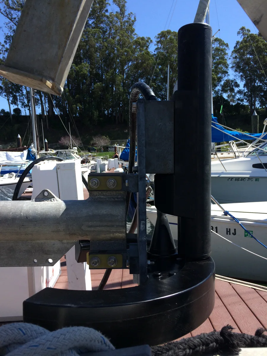
A patch test result is only valid for the specific physical configuration it was measured against. Pole-mounted transducers, which flex and shift more than a permanently through-hull installation, generally need to be checked more often than hull-mounted systems, which are fixed in place and hold their calibration longer between checks. Any change to that configuration — a haul-out, a transducer remount, a change of survey vessel, or even a significant change in loading that shifts the vessel's trim — is a reason to re-run the test rather than trust a calibration performed under different physical conditions. Treating a patch test as a formality to complete once at the start of a mobilisation, rather than a configuration-specific measurement that needs revalidating whenever the configuration changes, is one of the more common ways an otherwise well-run survey quietly picks up a systematic bias it never needed to have.
Ten Minutes of Setup, Hours of Saved Rework
None of the four parameters a patch test measures are large in absolute terms — a couple of degrees here, a few tens of milliseconds there. But because a multibeam echosounder projects those small angular errors out across an entire swath, and because a survey typically stitches together dozens or hundreds of overlapping lines, an uncorrected patch test doesn't produce one bad sounding — it produces a consistent, compounding bias across the entire dataset. The test itself takes a few hours at the start of a mobilisation. Finding and explaining an unexplained systematic offset after a client has already received the final surface, by contrast, takes a great deal longer — which is exactly the trade the patch test exists to avoid.
References
- Godin, A. (1998), "The Patch Test: A Comprehensive Calibration Tool for Multibeam Echosounders," IEEE OCEANS Conference Proceedings, https://ieeexplore.ieee.org/document/882178/
- International Hydrographic Review (IHR), "Survey Systems Verification and Calibration in the Hydrospatial Domain," https://ihr.iho.int/articles/survey-systems-verification-and-calibration-in-the-hydrospatial-domain/
- Hydro International, "S-44 and the Systematic Error," https://www.hydro-international.com/content/article/s-44-and-the-systematic-error
- R2Sonic, "The Patch Test – Multibeam Calibration," https://www.r2sonic.com/wp-content/uploads/2020/03/The-New-Patch-Test.pdf
- NOAA Ocean Exploration, "Multibeam Calibration: Conducting a Patch Test," https://oceanexplorer.noaa.gov/wp-content/uploads/2023/04/patchtest-poster.pdf
- Hydro International, "Automatic Calibration for MBES Offsets," https://www.hydro-international.com/content/article/automatic-calibration-for-mbes-offsets
- Worldwide Survey Dynamics, "Patch Test – MBES Hydrographic Survey," https://wsd-survey.com/patch-test-mbes-hydrographic-survey-hydrospatial-roll-latency-pitch-yaw/
Related Articles
Applications of Multibeam Echosounders: From Single Soundings to Full 3D Seafloor Maps
Sound Velocity in Bathymetry: The Number Every Depth Measurement Depends On