Marine Survey Fundamentals
Sound Velocity in Bathymetry: The Number Every Depth Measurement Depends On
An echosounder never measures depth directly. What it actually measures is time — how long a sound pulse takes to travel down to the seafloor and back up. Depth is calculated from that time using one deceptively simple relationship: D = v·t/2, where v is the speed of sound in the water column. Get that one number wrong, and every depth the instrument reports is wrong by roughly the same proportion, no matter how precise the transducer or how expensive the system.
How Depth Is Actually Calculated
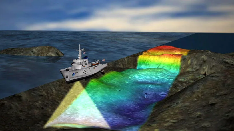
Every echosounder, from a single downward-pointing transducer to a wide-swath multibeam array, works on the same basic principle: send a sound pulse toward the seafloor, time how long it takes for the echo to return, and multiply that travel time by the speed of sound to get a distance. Divide by two because the sound has to travel down and back, and you have the formula every hydrographic textbook opens with: D = v·t/2. The travel time an instrument measures is extremely precise — modern electronics can resolve fractions of a millisecond. The weak link in that equation has never been the clock. It's v.
The Physics: Why Sound Doesn't Travel at One Speed Underwater
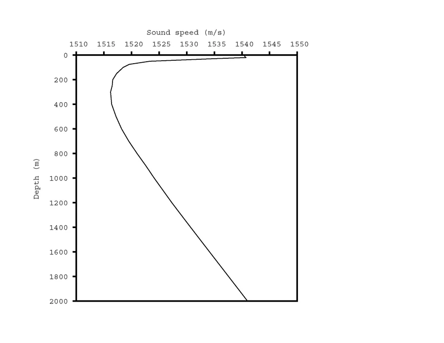
Sound speed in seawater is set by three variables acting at once: temperature, salinity, and pressure. Warmer water carries sound faster, so near the sun-warmed surface, sound speed is usually at its highest. Moving down through the thermocline — the layer where temperature drops quickly with depth — sound speed falls along with it, reaching a minimum a few hundred meters down in much of the open ocean. Below that point, temperature stops changing much, but pressure keeps climbing, and rising pressure pushes sound speed back up all the way to the seafloor. Salinity plays a smaller but real role throughout, nudging sound speed up as salt content increases. Because these three variables shift continuously with depth, plotting sound speed against depth at any one location produces a curve like the one in Figure 1 — a sound speed profile, unique to that place and moment, and the reason a single assumed velocity for an entire survey area is rarely good enough.
From Physics to Formula: Calculating Sound Speed
Turning temperature, salinity, and pressure readings into an actual sound speed number has a research history stretching back decades. Wilson (1960) produced the first widely used empirical equation, built from 581 measured sound speeds spanning fifteen temperatures, eight pressures, and five salinities, fitted into a 22-coefficient relationship with an accuracy of about 0.3 m/s. Chen and Millero (1977) refined the measurement at high pressure and salinity ranges relevant to the deep ocean, and their results became the basis for the UNESCO algorithm still treated as the international reference standard today. For situations where a simpler calculation is enough, Mackenzie (1981) published a nine-term equation compact enough to run on a pocket calculator, valid for temperatures of 2–30°C, salinities of 25–40 parts per thousand, and depths from 0 to 8,000 m:
c = 1448.96 + 4.591T − 0.05304T² + 0.0002374T³ + 1.340(S−35) + 0.0163D + 0.0000001675D² − 0.01025T(S−35) − 0.0000000000007139TD³
where c is sound speed in m/s, T is temperature in °C, S is salinity in parts per thousand, and D is depth in meters. None of these equations are theoretical derivations from first principles — they're empirical fits to painstakingly measured data, which is exactly why the input measurements (temperature, salinity, depth) have to be accurate for the output to mean anything.
Measuring It in the Field: Casts, Probes, and Real-Time Sensors
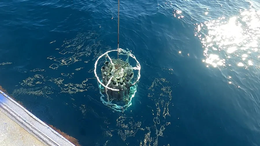
In practice, surveyors get their sound speed profile one of two ways. A CTD or a dedicated sound velocimeter is lowered through the water column on a winch, logging temperature, salinity (or conductivity), and pressure at close depth intervals as it descends — a cast that typically requires the vessel to stop or slow to a near-hover, taking on the order of half an hour depending on water depth. Where stopping isn't practical, a moving vessel profiler (MVP) uses a winch-controlled, free-falling body that can be deployed and retrieved while the ship keeps moving, repeating the cast roughly every 30 minutes instead of requiring a full stop each time. Because conditions can shift meaningfully within a single working day, sound velocity is typically re-measured multiple times during a survey rather than once at the start. Alongside full-depth casts, many systems also carry a surface sound velocity sensor (SVS) mounted at or near the transducer head, feeding a continuously updated near-surface value into the beam-steering calculation in real time — a complement to, not a replacement for, the deeper profile cast. These instruments themselves need periodic recalibration, typically checked in controlled fresh-water tanks where accuracy can be verified to around 0.02 m/s, well beyond what's achievable in a seawater test.
What Happens When the Number Is Wrong: Refraction Errors
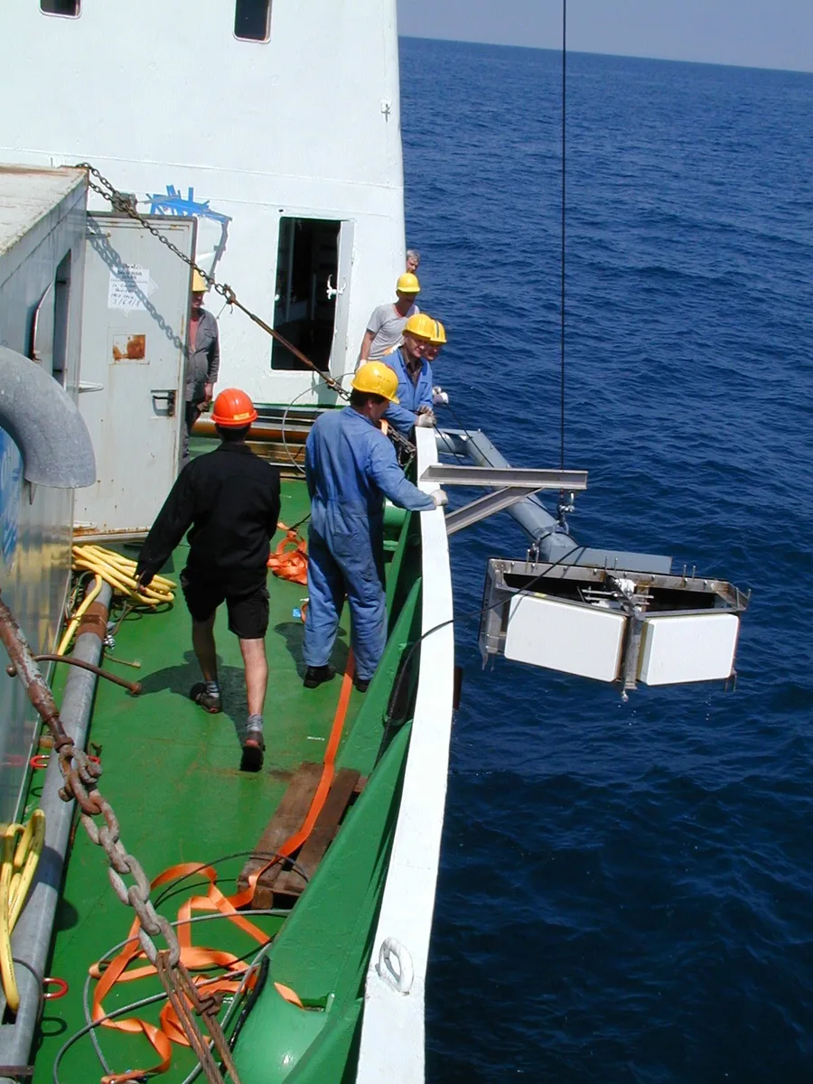
An echosounder pointed straight down and an echosounder steering beams out at a wide angle are affected very differently by a sound speed error. A single, near-vertical beam barely bends even if the assumed velocity is slightly off, because the path length error and the angular error are both small. A multibeam system sending dozens of beams across a wide swath has no such luxury: sound bends whenever it crosses a boundary between layers of different velocity, the same physical principle that bends light passing from air into water, and the further a beam travels off-nadir, the more that bending accumulates. When the sound velocity value used for processing is higher than the water actually supports, the outer beams end up displaced upward relative to the center, curling the swath into a shape surveyors call a "smile." When the assumed value is too low, the outer beams curl the other way, producing a "frown." Both are systematic, not random, artifacts — they appear consistently across an entire swath line and can be mistaken for real seafloor texture if the underlying velocity error isn't caught and corrected during processing.
Standards: Sound Velocity Inside IHO S-44
The International Hydrographic Organization's S-44 standard sets the maximum allowable Total Vertical Uncertainty (TVU) a depth measurement can carry at a 95% confidence level, expressed as TVU = ±√(a² + (b·d)²), where a is a fixed depth-independent term, b·d scales with water depth d, and the coefficients tighten as survey order increases — historically around a = 1.00 m, b = 0.023 for Order 2 surveys in deeper, lower-risk water, down to a = 0.25 m, b = 0.0075 for Special Order surveys in critical areas such as berths and channels with minimal underkeel clearance. Sound velocity error is explicitly one of the contributing components inside that uncertainty budget, alongside range error, beam angle error, vessel motion (pitch, roll, heave), draft, and water-level error — which is why S-44-compliant survey practice calls for sound velocity to be checked multiple times a day rather than assumed constant for the duration of a survey.
Conclusion
Depth, in hydrographic survey, is never a direct reading — it's a calculation, and sound velocity is the assumption baked into every single one of those calculations. A student learning bathymetry for the first time can memorize D = v·t/2 in a few seconds; understanding why v is the hardest part of that equation to get right — and what happens to a dataset when it's wrong — is what actually separates a depth number worth trusting from one that only looks confident.
References
- Wilson, W.D. (1960) — Equation for the Speed of Sound in Sea Water, Journal of the Acoustical Society of America, 32(10), 1357
- Chen, C-T. & Millero, F.J. (1977) — Speed of Sound in Seawater at High Pressures, Journal of the Acoustical Society of America, 62(5), 1129–1135
- Mackenzie, K.V. (1981) — Nine-Term Equation for Sound Speed in the Oceans, Journal of the Acoustical Society of America, 70(3), 807–812
- International Hydrographic Organization — S-44 Standards for Hydrographic Surveys (Total Vertical Uncertainty)
- U.S. Geological Survey — Sound Velocity Profiles from XBT/CTD Casts, USGS Field Activities 2017-001-FA and 2017-002-FA
- MDPI Energies (2021) — The Importance of Under-Keel Sound Velocity Sensor in Measuring Water Depth with Multibeam Echosounder
- Wikipedia — Sound Speed Profile
- U.S. Geological Survey — CTD Rosette Being Deployed; Deploying Multibeam Sonar
Related Articles